
For some number of weeks I’ve been experimenting with the Espressif ESP32-S3-DevKitC-1-N8R8 and ESP32-C3-DevKitC-02. I purchased them both from Adafruit. In this post I’m going to write about the ESP32-S3, or S3.
These boards with newish processors are marked as experimental with no mainline support either in the Arduino IDE nor Micro Python/Circuit Python. I initially tried to build a version of Micro Python from directions I found on the web that would work in the S3 board using the ESP-IDF tools, but while Micro Python would compile and load, it wouldn’t work. When I decided I’d wasted enough time trying to get Micro Python to work, I switched to the pure C/C++ development tools in the ESP-IDF with both platforms and found much success and satisfaction.
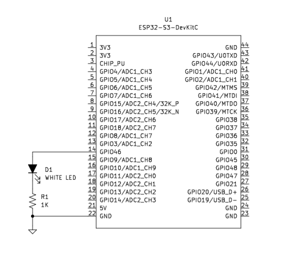
I turned to learning a bit more about using freeRTOS with the S3 board, and to that end I created a variant of the standard blink application I call dualblink. The code will blink the on-board NeoPixel as well as an off-board LED, as shown in the simple schematic diagram at the start of this post.
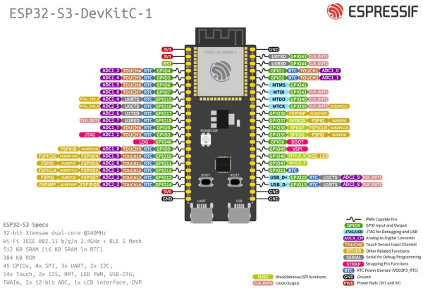
Since the board is powered by the micro USB port labeled UART in the image below, there is no other power attachment needed. All you need to hook up the external LED is the LED and a 1KΩ resister wired as shown above. Then compile the code using the ESP-IDF tool, idf.py, flash it to the device, and sit back and watch the blinkin’ lights.

This code started as an ESP-IDF example called blink. It’s evolved such that the code starts two tasks, one to blink the on-board NeoPixel LED and one to blink the off-board regular LED. The NeoPixel cycles through five colors and has a 1 second period with a 50% duty cycle (500ms on, 500ms off). The second LED task has a 1.1 second period with a 9% duty cycle (100 mS on, 1 second off). Both tasks are started in app_main(). The code should be pretty self-explanatory.
#include <stdio.h>#include "freertos/FreeRTOS.h"#include "freertos/task.h"#include "driver/gpio.h"#include "esp_log.h"#include "led_strip.h"#include "sdkconfig.h"static const char *TAG = "DUAL_BLINK";static void vTaskBlinkNeoPixel(void * pvParameters) {static led_strip_t *pStrip_a;pStrip_a = led_strip_init(CONFIG_BLINK_LED_RMT_CHANNEL, CONFIG_BLINK_GPIO, 1);pStrip_a->clear(pStrip_a, 50);static uint color_select = 0;#define NUM_COLORS 5static int led_colors[NUM_COLORS][4] = {{0, 32, 0, 0}, // red{0, 0, 32, 0}, // green{0, 0, 0, 32}, // blue{0, 32, 0, 16}, // violet{0, 0, 32, 32} // cyan};for( ;; ) {// Set NeoPixel LED to a color using RGB from 0 (0%) to 255 (100%)// for each color.//pStrip_a->set_pixel(pStrip_a, led_colors[color_select][0], led_colors[color_select][1], led_colors[color_select][2], led_colors[color_select][3]);color_select++;if (color_select >= NUM_COLORS) color_select = 0;// Refresh the strip to send data//pStrip_a->refresh(pStrip_a, 100);vTaskDelay(500 / portTICK_PERIOD_MS);// Set NeoPixel LED dark by clearing all its pixels.pStrip_a->clear(pStrip_a, 50);vTaskDelay(500 / portTICK_PERIOD_MS);}}static void vTaskBlinkLED(void * pvParameters) {#define BLINK_GPIO46_LED 46gpio_reset_pin(BLINK_GPIO46_LED);// Set the GPIO as a push/pull outputgpio_set_direction(BLINK_GPIO46_LED, GPIO_MODE_OUTPUT);for ( ;; ) {gpio_set_level(BLINK_GPIO46_LED, true); // LED onvTaskDelay(100 / portTICK_PERIOD_MS);gpio_set_level(BLINK_GPIO46_LED, false); // LED offvTaskDelay(2000 / portTICK_PERIOD_MS);}}void app_main(void) {int core = xPortGetCoreID();ESP_LOGI(TAG, "app_main running on core %i", core);ESP_LOGI(TAG, "CONFIG_BLINK_GPIO %i", CONFIG_BLINK_GPIO);// BaseType_t xReturned;TaskHandle_t xHandle = NULL;static uint8_t ucParameterToPass = 1;xTaskCreate(vTaskBlinkNeoPixel,"BlinkNeoPixel",2048,&ucParameterToPass,tskIDLE_PRIORITY,&xHandle);configASSERT(xHandle);TaskHandle_t xHandle2 = NULL;static uint8_t ucParameterToPass2 = 1;xTaskCreate(vTaskBlinkLED,"BlinkLED",2048,&ucParameterToPass2,tskIDLE_PRIORITY,&xHandle2);configASSERT(xHandle2);while (true) {vTaskDelay(1000 / portTICK_PERIOD_MS);}}Here’s what a typical run looks like when you run idf.py -p /dev/ttyUSB0 flash monitor.
SP-ROM:esp32s3-20210327Build:Mar 27 2021rst:0x1 (POWERON),boot:0x8 (SPI_FAST_FLASH_BOOT)SPIWP:0xeemode:DIO, clock div:1load:0x3fcd0108,len:0x16e4load:0x403b6000,len:0xb7cload:0x403ba000,len:0x2f90entry 0x403b6248I (24) boot: ESP-IDF v5.0-dev-1554-g20847eeb96-dirty 2nd stage bootloaderI (25) boot: compile time 21:55:49I (25) boot: chip revision: 0I (28) boot.esp32s3: Boot SPI Speed : 80MHzI (33) boot.esp32s3: SPI Mode : DIOI (38) boot.esp32s3: SPI Flash Size : 2MBI (43) boot: Enabling RNG early entropy source...I (48) boot: Partition Table:I (52) boot: ## LabelUsage Type ST Offset LengthI (59) boot: 0 nvs WiFi data01 02 00009000 00006000I (66) boot: 1 phy_init RF data 01 01 0000f000 00001000I (74) boot: 2 factory factory app 00 00 00010000 00100000I (81) boot: End of partition tableI (86) esp_image: segment 0: paddr=00010020 vaddr=3c020020 size=09148h ( 37192) mapI (101) esp_image: segment 1: paddr=00019170 vaddr=3fc919c0 size=027a4h ( 10148) loadI (105) esp_image: segment 2: paddr=0001b91c vaddr=40374000 size=046fch ( 18172) loadI (115) esp_image: segment 3: paddr=00020020 vaddr=42000020 size=19414h (103444) mapI (138) esp_image: segment 4: paddr=0003943c vaddr=403786fc size=092bch ( 37564) loadI (147) esp_image: segment 5: paddr=00042700 vaddr=50000000 size=00010h (16) loadI (152) boot: Loaded app from partition at offset 0x10000I (152) boot: Disabling RNG early entropy source...I (167) cpu_start: Pro cpu up.I (167) cpu_start: Starting app cpu, entry point is 0x403751c40x403751c4: call_start_cpu1 at /home/popos/Develop/esp/esp-idf/components/esp_system/port/cpu_start.c:152I (0) cpu_start: App cpu up.I (181) cpu_start: Pro cpu start user codeI (181) cpu_start: cpu freq: 240000000 HzI (181) cpu_start: Application information:I (184) cpu_start: Project name: dualblinkI (189) cpu_start: App version: 1I (193) cpu_start: Compile time: Mar 21 2022 21:55:46I (199) cpu_start: ELF file SHA256: 47cfacc829e236ab...I (205) cpu_start: ESP-IDF: v5.0-dev-1554-g20847eeb96-dirtyI (213) heap_init: Initializing. RAM available for dynamic allocation:I (220) heap_init: At 3FC94B98 len 0004B468 (301 KiB): D/IRAMI (226) heap_init: At 3FCE0000 len 0000EE34 (59 KiB): STACK/DRAMI (233) heap_init: At 3FCF0000 len 00008000 (32 KiB): DRAMI (239) heap_init: At 600FE000 len 00002000 (8 KiB): RTCRAMI (246) spi_flash: detected chip: genericI (250) spi_flash: flash io: dioW (254) spi_flash: Detected size(8192k) larger than the size in the binary image header(2048k). Using the size in the binary image header.I (267) sleep: Configure to isolate all GPIO pins in sleep stateI (274) sleep: Enable automatic switching of GPIO sleep configurationI (281) cpu_start: Starting scheduler on PRO CPU.I (0) cpu_start: Starting scheduler on APP CPU.I (301) DUAL_BLINK: app_main running on core 0I (301) DUAL_BLINK: CONFIG_BLINK_GPIO 48I (321) gpio: GPIO[46]| InputEn: 0| OutputEn: 0| OpenDrain: 0| Pullup: 1| Pulldown: 0| Intr:0
Note that the cpu frequency is 240 MHz (line 37). This is selected through idf.py menuconfig and then Component config -> ESP32S3-Specific -> CPU frequency. The default is currently 160 MHz even though the board is sold with an advertised 240 MHz operational frequency.
References
- Adafruit — Espressif ESP32-S3-DevKitC-1-N8R8 — https://www.adafruit.com/product/5336
- Espressif KiCad Library — https://github.com/espressif/kicad-libraries
- Espressif ESP32-S3-DevKitC-1 Getting Started — https://docs.espressif.com/projects/esp-idf/en/latest/esp32s3/hw-reference/esp32s3/user-guide-devkitc-1.html
- Espressif FreeRTOS System API — https://docs.espressif.com/projects/esp-idf/en/latest/esp32/api-reference/system/freertos.html
- Espressif ESP-IDF on GitHub — https://github.com/espressif/esp-idf

You must be logged in to post a comment.