It’s been a long strange trip to this post, across many years and many little personal projects. Let’s start here to de-tangle some of it.
Back in the late 2010s (2018 or so) I started purchasing Adafruit boards which included Circuit Playground as well as several Feather boards. They all came preloaded with CircuitPython, Adafruit’s fork of MicroPython. The boards were easy to program with embedded Python and the tools, while simple, were solid. What I appreciated most (and still do) is how the boards, when plugged into a host computer via USB, appear as a drive on the host system. You can then edit CircuitPython code directly on the device, and if it’s running when you save a new version, the device will note the file system change and restart with the version of your code you just saved. You can use any editor on the host system you desire and are already familiar with. The only other tool needed on the host system for development is a serial application that can work with the Adafruit device’s USB serial port. With that application you have a full Python REPL to work with, and when the application is running, you can see any printed outputs or see when and where you have a CircuitPython coding error.
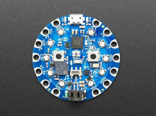
The last time I worked with those boards was back in 2019, before I retired and before the Pandemic and Lockdown took hold. They went into my gadget storage and stayed there until earlier this week. I was looking for another device that had Bluetooth capabilities, so of course when I unearthed the Bluefruit in my stash I pulled it out and plugged it in. It started up just fine, except the Bluetooth code section I’d written did nothing. I opened the boot_out.txt file on the device’s flash device and read it was still running with CircuitPython 7.2. The current CircuitPython release is 8.2.9, a rather wide difference between versions. So I decided I’d stop and upgrade the device’s CircuitPython.
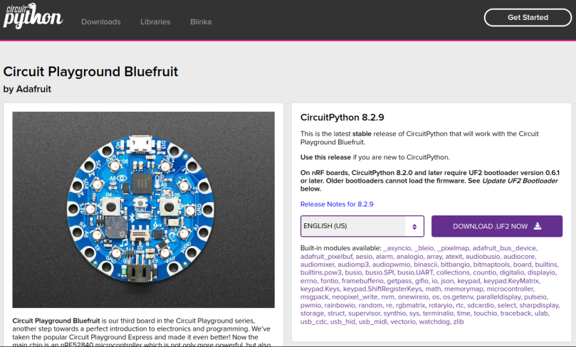
Circuit Playground Bluefruit Circuit Python page
When you arrive at the CircuitPython download page ( https://circuitpython.org/board/circuitplayground_bluefruit/ ) for the Bluefruit you’re presented with a very clear warning about the device’s bootloader. Since I knew without looking that my copy of Bluefruit would need a bootloader update, I scrolled down to the part at the very bottom that spoke of how to update the bootloader.
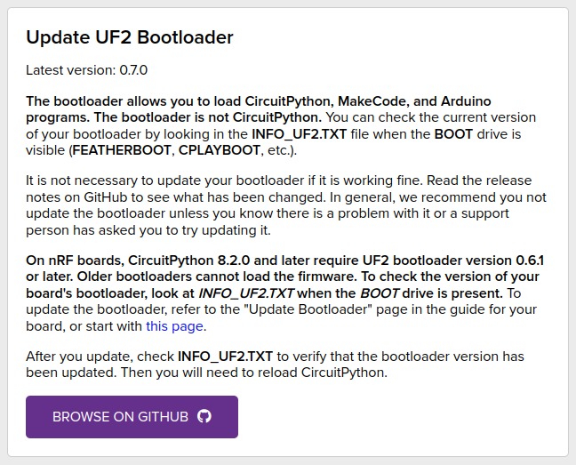
CircuitPython Bootloader Update Instructoins
At this section things begin to get a little murky. There’s a cautionary note to start off about how to find out what bootloader version you have and not to update unless you have to (I knew I had to) and then two links off the page, one to generic instructions and a big button to browse the bootloader repo. I’ll cut to the chase.
Long story short, after several failed attempts following directions before the command line instructions, I managed to update the bootloader and then update my Bluefruit to CircuitPython 8.2.9. I did all of this under Linux Mint, and it went swimmingly. When it powered back up the Bluetooth section failed to run with a coding error, so I disabled the one call to that module with a single comment and let the rest of it execute. I’ve now got two boards I need to investigate Bluetooth functionality. But, hey, it’s just a hobby, right?
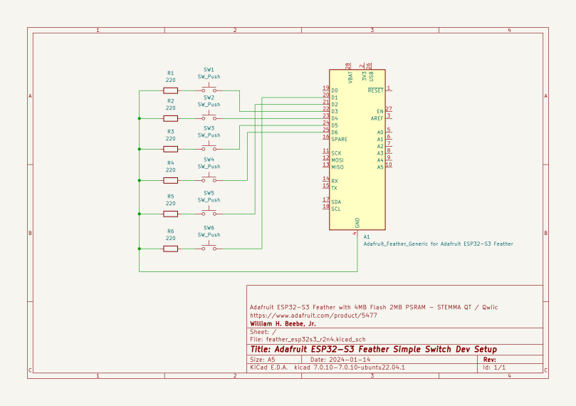
When I start to develop an embedded system, I always try to construct a test layout or mockup of what I envision the final product will be. A test system can embody an important subset of requirements, and I can begin to write code for that final system. I can develop a lot more quickly with a mockup, and I can use the mockup to help debug issues during the phase where a more representative version of the end product arrives and I start to work with it. This is a simple mockup constructed of six switches and an Adafruit ESP32-S3 Feather running CircuitPython (code is listed further down). What I was developing with the mockup was the ability to read switch closures and to use the ESP32-S3’s WiFi radio to send switch status changes (open and close) to a central Linux system via a UCP socket.
I’m providing the official ESP32-S3 Feather pinout diagram from Adafruit because the generic part provided by KiCad is too generic and too old. The specific pin numbers are correct, but not much else.
## Adafruit ESP32-S3 Feather with 4MB Flash 2MB PSRAM - STEMMA QT / Qwiic# https://www.adafruit.com/product/5477#import boardimport osimport gcimport binasciiimport microcontroller as miimport wifiimport socketpoolimport crc## Show ESP32-S3 Feather basic resource usage.#PLATFORM = ', '.join(os.uname())NAME = os.uname()[0]UNIQUE_ID = binascii.hexlify(mi.cpu.uid).decode('ascii').upper()SSID = NAME + '-' + UNIQUE_ID[-4:]print(f"PLATFORM: {PLATFORM}")print(f"FREE MEM: {gc.mem_free():,} BYTES")stat_vfs = os.statvfs('/')fs_total = stat_vfs[0] * stat_vfs[2]fs_free = stat_vfs[0] * stat_vfs[3]print(f"FS TOTAL: {fs_total:,} BYTES")print(f"FS FREE: {fs_free:,} BYTES")print(f" UID: {UNIQUE_ID}")print(f"SSID: {SSID}")print(f"FREQ: {mi.cpu.frequency:,} Hz")print(f"FREE MEM: {gc.mem_free():,} BYTES")# Scan for WiFi networks. Sort list on RSSI strength.#print("\nWIFI: SCAN, SORTED BY RSSI")networks = []for network in wifi.radio.start_scanning_networks():networks.append(network)wifi.radio.stop_scanning_networks()networks = sorted(networks, key=lambda net: net.rssi, reverse=True)for network in networks:print(f"SSID: {network.ssid:<24}- RSSI: {network.rssi}")gc.collect()print(f"FREE MEM: {gc.mem_free():,} BYTES")import timeimport boardimport neopixelnp = neopixel.NeoPixel(board.NEOPIXEL, 1)# Cycle through five NeoPixel colors, then# turn off the NeoPixel#neopixel_colors = [(64, 0, 0), # red(0, 64, 0), # green(0, 0, 64), # blue(64, 32, 0), # orange(0, 64, 64), # cyan(0, 0, 0)# black]def cycle_colors():for color in neopixel_colors:np.fill(color)np.write()time.sleep(0.4)np.fill(neopixel_colors[-1])np.write()print("NEOPIXEL: TESTING")cycle_colors()gc.collect()print(f"FREE MEM: {gc.mem_free():,} BYTES")import boardimport digitalio## Configure digital input triggers.#input_1 = digitalio.DigitalInOut(board.D10)input_1.switch_to_input(pull=digitalio.Pull.DOWN)input_2 = digitalio.DigitalInOut(board.D11)input_2.switch_to_input(pull=digitalio.Pull.DOWN)input_3 = digitalio.DigitalInOut(board.D12)input_3.switch_to_input(pull=digitalio.Pull.DOWN)input_4 = digitalio.DigitalInOut(board.D13)input_4.switch_to_input(pull=digitalio.Pull.DOWN)input_5 = digitalio.DigitalInOut(board.D9)input_5.switch_to_input(pull=digitalio.Pull.DOWN)input_6 = digitalio.DigitalInOut(board.D6)input_6.switch_to_input(pull=digitalio.Pull.DOWN)import ipaddressfrom adafruit_httpserver.server import HTTPServerfrom adafruit_httpserver.response import HTTPResponseudp_host = Noneudp_port = Nonetry:print("WIFI: CONNECT IN PROGRESS TO", os.getenv("AP_SSID"))wifi.radio.hostname = SSIDif os.getenv("ADDRESS") is not None:ipv4 = ipaddress.IPv4Address(os.getenv("ADDRESS"))netmask = ipaddress.IPv4Address(os.getenv("NETMASK"))gateway = ipaddress.IPv4Address(os.getenv("GATEWAY"))wifi.radio.set_ipv4_address(ipv4=ipv4, netmask=netmask, gateway=gateway)print("WIFI: STATIC ADDRESS USED")wifi.radio.connect(os.getenv("AP_SSID"), os.getenv("AP_PASSWORD"))print("WIFI: SUCCESSFUL CONNECT")print(" IP ADDR:", wifi.radio.ipv4_address)print(" IP GWAY:", wifi.radio.ipv4_gateway)print(" IP SNET:", wifi.radio.ipv4_subnet)print("HOSTNAME:", wifi.radio.hostname)## Set up a UDP socket for sending out messages.#pool = socketpool.SocketPool(wifi.radio)udp_host = str(os.getenv("UDP_HOST"))udp_port = int(os.getenv("UDP_PORT"))sock = pool.socket(pool.AF_INET, pool.SOCK_DGRAM)print("WIFI: UDP SOCKET CREATED")if os.getenv("PING_TEST") is not None:ping_test_addr = os.getenv("PING_TEST")ping_test = ipaddress.ip_address(ping_test_addr)for i in range(5):print("WIFI: PING TEST",ping_test_addr,"-",(wifi.radio.ping(ping_test)*1000),"MS")time.sleep(1)except Exception as e:print("WIFI: FAILURE")print("WIFI: REASON:", e)delay = float(os.getenv("DELAY"))print(" DELAY:", delay, "seconds")print(" ACTION: WAITING FOR DIGITAL EVENTS")i1flag = Falsei2flag = Falsei3flag = Falsei4flag = Falsei5flag = Falsei6flag = Falseindicator_counter = 0max_count = int(os.getenv("MAX_COUNT"))## Use an ordered dictionary so we can have# an ordered readable JSON message.#import jsonfrom collections import OrderedDictjson_template = OrderedDict([("IO",OrderedDict([("ID", SSID), ("S1", False),("S2", False), ("S3", False), ("S4", False),("S5", False), ("S6", False)]))])print("JSON MSG:", json.dumps(json_template))print(" UDP:", udp_host, udp_port)def send_udp_message(name, value):json_template["IO"][name] = valueudp_message = bytearray(json.dumps(json_template), 'utf-8')sock.sendto(bytes(udp_message), (udp_host, udp_port))while True:if indicator_counter > max_count:indicator_counter = 0np.fill(neopixel_colors[1])np.write()else:indicator_counter += 1np.fill(neopixel_colors[-1])np.write()if input_1.value and not i1flag:send_udp_message("S1", True);i1flag = Trueelif not input_1.value and i1flag:send_udp_message("S1", False);i1flag = Falseif input_2.value and not i2flag:send_udp_message("S2", True)i2flag = Trueelif not input_2.value and i2flag:send_udp_message("S2", False)i2flag = Falseif input_3.value and not i3flag:send_udp_message("S3", True)i3flag = Trueelif not input_3.value and i3flag:send_udp_message("S3", False)i3flag = Falseif input_4.value and not i4flag:send_udp_message("S4", True)i4flag = Trueelif not input_4.value and i4flag:send_udp_message("S4", False)i4flag = Falseif input_5.value and not i5flag:send_udp_message("S5", True)i5flag = Trueelif not input_5.value and i5flag:send_udp_message("S5", False)i5flag = Falseif input_6.value and not i6flag:send_udp_message("S6", True)i6flag = Trueelif not input_6.value and i6flag:send_udp_message("S6", False)i6flag = Falsetime.sleep(delay)
The code is rather long, with a lot of debugging information that is displayed on a monitoring terminal. I don’t normally turn all that off because these devices aren’t attached to a terminal during regular operation. If anything, the power is supplied via the Feather’s battery input with something more sophisticated than a bare battery.
The interesting code starts at line 151, where we set up the JSON dictionary structure, than at line 175 where we stay in a loop polling for switch state changes. The only event that needed alerting was if the switch was open and then it closed, or if closed and then opened. I wasn’t required to note momentary closures. I got away with push buttons on my mockup because it was what I had at hand, and a second or so on the push button was more than adequate for testing. Out in the field the switches were more like toggle switches.
Here’s what it looks like when it runs. I’m using Thonny’s terminal to capture the output;
PLATFORM: ESP32S3, ESP32S3, 8.2.9, 8.2.9 on 2023-12-06, Adafruit Feather ESP32S3 4MB Flash 2MB PSRAM with ESP32S3FREE MEM: 2,036,384 BYTESFS TOTAL: 2,404,352 BYTESFS FREE: 2,352,128 BYTES UID: 4F21AF95CC4DSSID: ESP32S3-CC4DFREQ: 240,000,000 HzFREE MEM: 2,035,984 BYTESWIFI: SCAN, SORTED BY RSSISSID: GuestNetwork- RSSI: -47SSID: g00gleeeyes - RSSI: -48SSID: ESP32S3-4EF0- RSSI: -48SSID: DIRECT-FF-HP OfficeJet Pro 9020- RSSI: -55SSID: SmartLife-EEFB - RSSI: -76SSID: asus 2.4- RSSI: -84SSID: Miller guest- RSSI: -85SSID: christian173- RSSI: -85SSID: Dashmeister - RSSI: -85SSID: SpectrumSetup-4A- RSSI: -88SSID: Miller guest- RSSI: -89SSID: christian173- RSSI: -92SSID: NETGEAR80 - RSSI: -93FREE MEM: 2,036,400 BYTESNEOPIXEL: TESTINGFREE MEM: 2,034,272 BYTESWIFI: CONNECT IN PROGRESS TO g00gleeeyesWIFI: SUCCESSFUL CONNECT IP ADDR: 192.168.0.203 IP GWAY: 192.168.0.1 IP SNET: 255.255.255.0HOSTNAME: ESP32S3-CC4DWIFI: UDP SOCKET CREATED DELAY: 0.3 seconds ACTION: WAITING FOR DIGITAL EVENTSJSON MSG: {"IO": {"ID": "ESP32S3-CC4D", "S1": false, "S2": false, "S3": false, "S4": false, "S5": false, "S6": false}} UDP: 192.168.0.248 23456
When I write MicroPython code for one of the embedded boards I have boilerplate code that helps identify the board (to make sure) as well as give me a clue to the environment I’m working in. The WiFi scan is my home WiFi environment, which includes neighbors on both sides as well as across the back of my yard. The first four lines are devices in my house. The rest are from locations outside my home. In my neighborhood we live on 1/3 to 1/2 acre plots of land, so it’s always surprising to me to see so many WiFi radios pop up. My close neighbors should be out of range, but it would appear they are not.
Starting at line 27 in the output, the Feather is attempting to connect to my local Linux host. First it joins my local home network via DHCP, it gets an IP address, then it attempts to create a UDP socket, which it does. The last line is the UPD IP address and port number it connects to. How do I know what IP address to use? It’s a two step process, starting with determining my Linux host’s IP address, and then editing a TOML file on the Feather.
## Variables AP_SSID and AP_PASSWORD must always be defined# with a valid access point SSID and PASSWORD.## Error from invalid AP_SSID: No network with that ssid# Error from invalid AP_PASSWORD: Unknown failure 15#AP_SSID="SSID"AP_PASSWORD="PASSWORD"## Uncomment the three environmental variables ADDRESS,# GATEWAY, and NETMASK for static IP address resolution.## ADDRESS is the class 5 IP address for the device.# GATEWAY is the IP address for the access point you want to connect to.# NETMASK is for the local device for further subnetting.## If ADDRESS is left commented then DHCP rules will be used.##ADDRESS="192.168.0.128"#GATEWAY="192.168.0.1"#NETMASK="255.255.255.0"## To not execute a ping test, comment out PING_TEST# This ping test is direct to Google# Error from invalid PING_TEST: unsupported types for __mul__: 'NoneType', 'int'##PING_TEST="8.8.4.4"## DELAY is how long to wait between scans of the digital inputs.# DELAY is in decimal floating point seconds.# To delay in milliseconds, use a fraction,# such as 0.3 for 300 milliseconds.## MAX_COUNT is how many DELAYs to wait before toggling the health# NeoPixel LED for a period of one DELAY.#DELAY="0.3"MAX_COUNT="20"## UDP support#UDP_HOST="192.168.0.248"UDP_PORT="23456"
There’s far more commentary than definitions, but that’s OK, especially if you’re going to hand this off to someone else to maintain. Starting with Circuit Python 8.0, Circuit Python will look for the text file settings.toml and automatically read in name/value pairs from it. This is the equivalent to defining environmental variables in a shell environment. This comes in quite handy as it eliminates having important information buried in the code. Before settings.toml the typical solution for constants was to define them in a Circuit Python file (such as secrets.py) and include that. It doesn’t mean you still can’t do that, but settings.toml is a bit cleaner.
On the system side I run this small bit of Python code to receive the Feather’s JSON messages.
#!/usr/bin/env pythonimport signalimport sysimport socketdef sigint_handler(signal, frame):print()sys.exit(0)signal.signal(signal.SIGINT, sigint_handler)# My home environment#hostname = socket.gethostname()ip_addr = socket.gethostbyname(hostname)print(f" Host {hostname} listening on IP address {ip_addr}")udp_port = 23456sock = socket.socket(socket.AF_INET, socket.SOCK_DGRAM) # UDPsock.bind((ip_addr, udp_port))print(f" Waiting for JSON messages on IP address {ip_addr}, port {udp_port}")while True: data, addr = sock.recvfrom(1024) # buffer size is 1024 bytes print(f" JSON message: {str(data, 'utf8')}")
The Python code’s only purpose is to wait for, receive, and then print out what it receives. With test_receive_udp.py running in a terminal, when I go back and toggle switch 1 attached to the Feather closed and then open again, I get the following output;
Host mint-prime listening on IP address 192.168.0.248 Waiting for JSON messages on IP address 192.168.0.248, port 23456 JSON message: {"IO": {"ID": "ESP32S3-CC4D", "S1": true, "S2": false, "S3": false, "S4": false, "S5": false, "S6": false}} JSON message: {"IO": {"ID": "ESP32S3-CC4D", "S1": false, "S2": false, "S3": false, "S4": false, "S5": false, "S6": false}}
It’s not as sexy as lights flashing, but it still fulfills an import task, which is to transmit a state change in a switch to another system for further processing, whatever I want that processing to be. While this lives on, with necessary changes, in another device out in the wild, I intend to use this to monitor various areas around my house, in particular whether my garage door is open or closed. I can forget to put the door down if I get distracted, especially in the evening. I want to know, without a doubt, the state of the garage door. I can do the same with other areas around the house. Right now my idea is to use one of my encased Raspberry Pi 4’s that I currently have attached, but doing relatively nothing, being the hub for microcontrollers such as this one.
There’s a lot I can do with this design, such as working on automatic bi-directional socket connectivity. That way I could send responses back to the microcontroller and have it execute arbitrary tasks. If this sounds like an alternative to Bluetooth and my MAX7219 displays, it is. It also brings to my mind a lot of different ways to build out remote sensors around my home.


You must be logged in to post a comment.